Description
Model GA
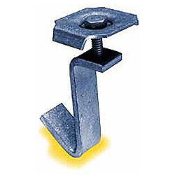
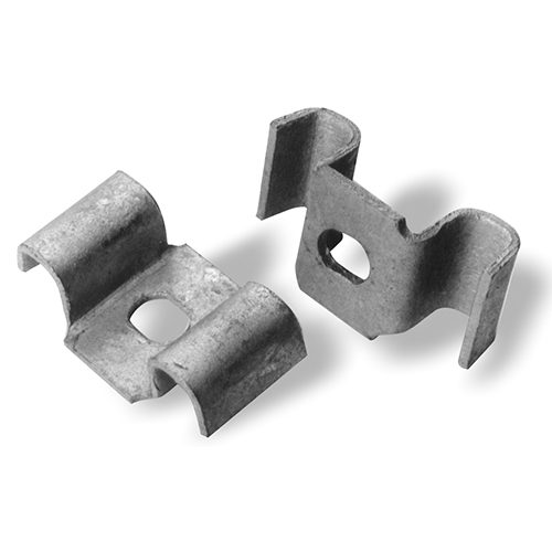
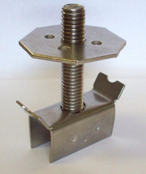
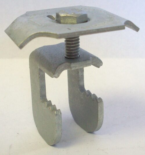
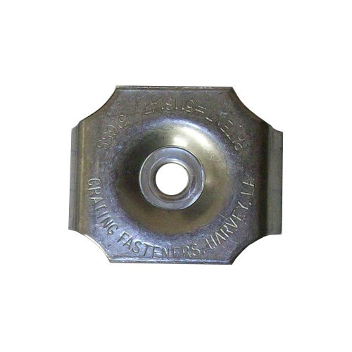
G-Clips model GA- fastener consists of three parts, which are assembled at the factory into a complete installation unit, packed 50 pieces into a standard box. The principal part is the lower body assembly, a J-shaped assembly with a female thread, which hooks under the underside of (vertical) structural shape. The second part is the stamped top, which fits over the grating upper surface. The body and top are joined by a 1/4″ – 20 threaded bolt, in proper length for the application.
INSTALLATION PREPARATION
As with any grating fastener, care should be taken during the grating layout, cutting and placement phase to reduce the quantity of grating cross bars that are located over the structural member flange edge. This reduces the quantity of grating cross bars that interfere with fastener placement, which otherwise requires cutting of cross bars.
TOOLS REQUIRED
G-Clips can be installed using a handheld 7/16″ nut driver.
INSTALLATION GUIDE
Hold the G-Clip square top in hand, allowing the body to hang downward. Fit the body between two bearing bars and lower the unit until the body is below the grating bottom. The downward-hanging shape must be hooked under the vertical member and drawn upward, while the fastener bolt is tightened. Pull upward on the top of the G-Clip, holding upward force, with the formed lower-body secure under the structural member. Tighten bolt to complete the installation of the G-Clip unit.
TORQUE REQUIREMENTS
Common handheld nut drivers have a handle diameter or 1″ to 1-1/4″, which will allow installation torque of approximately 60 inch/pounds to be easily achieved. This is sufficient for many installation requirements. Electrical or pneumatic-driven tools are often used on large grating surface areas. Do not exceed torque values of 150 inch/pounds, if fastener reuse is desired.
HOW TO ORDER
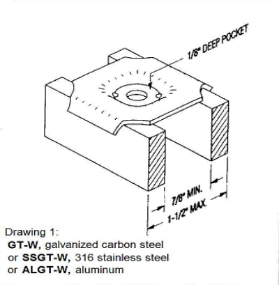
Determine the total height of grating, and the thickness of the flange area.


Reviews
There are no reviews yet.